Easy and best software for designing (3D modelling) -
There are many software solutions with advanced features that will allow you to work on really technical projects. Here is our selection of the best software to work with for mechanical engineering projects. Find out all the modeling and design tools that you need.
Some 3D software solutions really have amazing rendering tools. Using visualisation software or 3D modeling software with great visualisation options can help you to get a better overview of your project. Indeed, getting a good and precise overview of a technical project before the manufacturing process will allow you to adjust and improve your parts efficiently. It is also a good method to correct the last errors that you have maybe missed while 3D designing.
You need to find the best way to design a concept and show it to your customers? 3D visualisation is certainly the best method you could find! You can easily modify your model with your ideas, and the customer’s inputs.
If you are working on mechanical projects, you certainly know that design and analysis are essential. That is why we recommend you to use software with great analysis features, or another software tool, entirely dedicated to simulation and analysis, such as ANSYS..
1.Catia V5-


Commonly referred to as a 3D product Life cycle management software suite, CATIA supports multiple stages of product development, including (CAE) and manufacturing (CAM). CATIA facilitates collaborative engineering across disciplines around its 3D-EXPERIENCE platform, including surfacing & shape design, electrical, fluid and electronic systems design, mechanical engineer and system engineer.
CATIA facilitates the design of electronic, electrical, and distributed systems such as fluid and HVAC systems, all the way to the production of documentation for manufacturing.
CATIA enables the creation of 3D parts, from 2D sketches, sheet-metal, composites, molded, forged or tooling parts up to the definition of mechanical assemblies. The software provides advanced technologies for mechanical surfacing & BIW. It provides tools to complete product definition, including functional tolerances as well as kinematics definition.
CATIA provides a wide range of applications for tooling design, for both generic tooling and mold & die. In the case of Aerospace engineering an additional module named the aerospace sheet-metal design offers the user combine the capabilities of generative sheet-metal design and generative surface design.
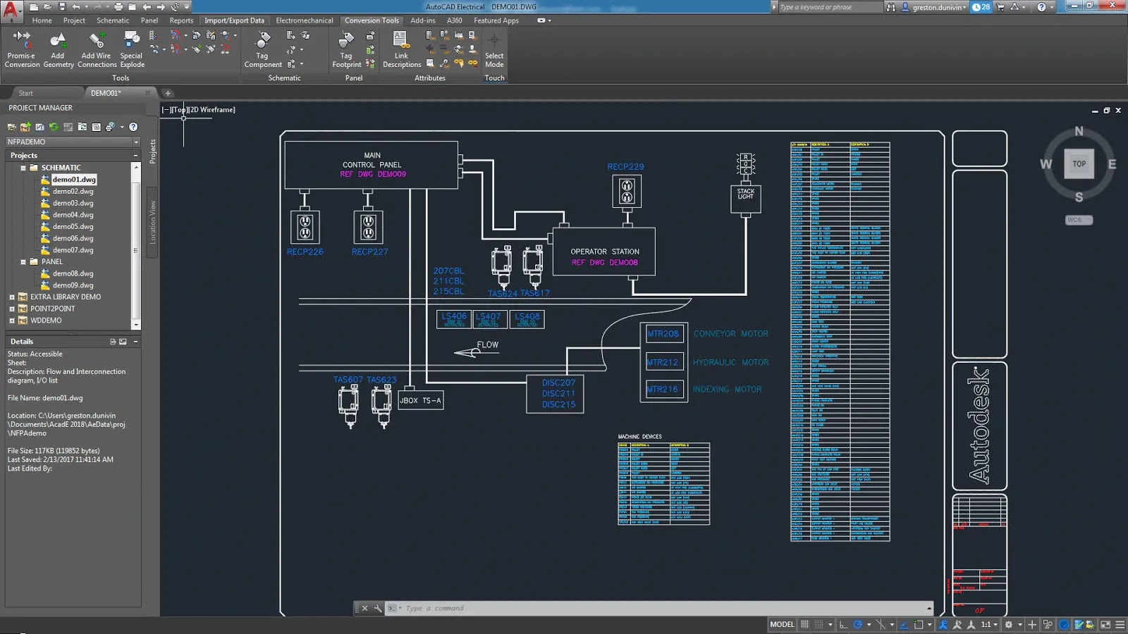
2.Auto CAD-


Autocad is a Commercial computer Aided-Design (CAD) and drafting software application. Developed and marketed by Autodesk, AutoCAD was first released in December 1982 as a desktop app running on microcomputers with internal graphic controllers Before AutoCAD was introduced, most commercial CAD programs ran on mainframe computers or minicomputers, with each CAD operator (user) working at a separate graphics terminal Since 2010, AutoCAD was released as a mobile and web app as well, marketed as AutoCAD 360.
3.SolidWorks-


Some other softwares for designing-
CATIA provides a wide range of applications for tooling design, for both generic tooling and mold & die. In the case of Aerospace engineering an additional module named the aerospace sheet-metal design offers the user combine the capabilities of generative sheet-metal design and generative surface design.
2.Auto CAD-
Autocad is a Commercial computer Aided-Design (CAD) and drafting software application. Developed and marketed by Autodesk, AutoCAD was first released in December 1982 as a desktop app running on microcomputers with internal graphic controllers Before AutoCAD was introduced, most commercial CAD programs ran on mainframe computers or minicomputers, with each CAD operator (user) working at a separate graphics terminal Since 2010, AutoCAD was released as a mobile and web app as well, marketed as AutoCAD 360.
3.SolidWorks-

Building a model in SolidWorks usually starts with a 2D sketch (although 3D sketches are available for power users). The sketch consists of geometry such as points, lines, arcs, conics (except the hyperbola), and splines. Dimensions are added to the sketch to define the size and location of the geometry. Relations are used to define attributes such as tangency, parallelism, perpendicularity, and concentricity. The parametric nature of SolidWorks means that the dimensions and relations drive the geometry, not the other way around. The dimensions in the sketch can be controlled independently, or by relationships to other parameters inside or outside the sketch.
In an assembly, the analog to sketch relations are mates. Just as sketch relations define conditions such as tangency, parallelism, and concentricity with respect to sketch geometry, assembly mates define equivalent relations with respect to the individual parts or components, allowing the easy construction of assemblies. SolidWorks also includes additional advanced mating features such as gear and cam follower mates, which allow modeled gear assemblies to accurately reproduce the rotational movement of an actual gear train.
Finally, drawings can be created either from parts or assemblies. Views are automatically generated from the solid model, and notes, dimensions and tolerances can then be easily added to the drawing as needed. The drawing module includes most paper sizes and standards (ANSI, ISO,DIN, GOST, JIS, BSI and SAC).
4.SolidEdge-

SolidEdge is a 3D CAD, parametric feature (history based) and synchronous technology solid modeling software. It runs on Microsoft windows and provides solid modeling, assembly modeling and 2D orthographic views functionality for mechanical designers.
Solid Edge is developed by Siemens. It is the perfect 3D software for engineers for complex projects but also to give shape quite quickly to your ideas. It has a great 2D orthographic view functionality, really convenient for mechanical designers. It also has powerful engineering simulation capabilities for Computer-Aided Engineering.
This software is essential and will surely allow you to go further with all of your technical 3D projects.
5.Key creator-

KeyCreator is a non-parametric, non-history based, "direct" 2D/3D solid modeling CAD program.It was among the first CAD programs with 3D capabilities for personal computers. Besides solid modeling, KeyCreator is also capable of wire frame and surface modeling, as well as drafting.
You can both work on 2D and 3D projects with this CAD program in order to design engineering projects. This software tool has 3 different versions: Standard, Pro or Max, all offering different features. You will surely find the software package that will fit your project.
6.Autodesk Inventor-

Inventor allows 2D and 3D data integration in a single environment, creating a virtual representation of the final product that enables users to validate the form, fit, and function of the product before it is ever built. Autodesk Inventor includes powerful parametric, direct edit and freeform modeling tools as well as multi-CAD translation capabilities and in their standard DWG drawings. Inventor uses Shape manager, Autodesk's proprietary geometric modeling kernel. Autodesk Inventor competes directly with SolidWorks, Solid Edge and Creo.
7.Creo-

Creo is a family or suite of computer Aided-Design (CAD) apps supporting product design for discrete manufacturers and is developed by PTC. The suite consists of apps, each delivering a distinct set of capabilities for a user role within product development.
Creo runs on Microsoft windows and provides apps for 3D CAD parametric feature solid modeling, 3D direct modeling, 2D orthograpgic views, Finite Element Analysis and simulation, schematic design, technical illustrations, and viewing and visualization.
- Autodesk Design Product Suite
- ZW3D
- MechDesigner
- BricsCad
- Rhino
- Solid Face
- Top Solid Design
- Geometric design
- Ansys
- Patran
- Simulia
Comments
Post a Comment